Main Links
Sets Draw Type Main GallerymyFonttyper
myFonttyper
myFonttyper
myFonttyper
PNGs initial release was on the 1st October, 1996, almost 30 years ago now, and here we are, still using this file format every day. It latest release 3.0, was less than a month ago, 24th June 2025, showing that the support for this file format, has not disappeared whatsoever.
But, a lot of people do not even know how it works. We researched a lot, and now we are here to share our insights. Hold on tight, this is gonna be a deep dive, into pngs.
Before doing anything, it is appropriate to have the fitting security measurements in place, just to make sure that nothing goes wrong. PNGs themselves, are decompressed in a lossless way, meaning no data is lossed in the process of compressing it. Now, it would suck if the decompressor had to decompress every file, even if it isnt PNGs, right?
Exactly, that is why PNGs have a so-called SIGNATURE, at the start of their files. The magic
number "89 50 4e 47 0d 0a 1a 0a", is a 1 Byte signature, which when decoded spells ".PNG... "
or something like that. It is used by Software, to detect whether or not the file we are opening
is a PNG or not.
Here are some more Signatures from different formats;
GIF87a "47 49 46 38 37 61", GIF89a "47 49 46 38 39 61",
tif "49 49 2A 00", or
jpg "FF D8 FF E0 00 10 4A 46 49 46 00 01" / "FF D8 FF EE" / "FF D8 FF E0" / "FF D8 FF E1 ?? ??
45 78 69 66 00 00" (yeah idk either.)
Most files have their own signature, and their own decompiler checks it before, well, decompiling it.
But, what are the insides of a PNG?
The PNG is built with many chunks. Most of them have (in my opinion) quite a weird design, yet still seem to be somewhat efficient.
First off, we got the signature at the start of every single .png file;
"89 50 4E 47 0D 0A 1A 0A". This is always there.
Next, we got the so called IHDR (IMAGE HEADER). Before we continue, lets do a
different deep dive.
The PNG file format has many chunks. These chunks are divided into two sections;
The Ancillary chunks and the Critical chunks.
All chunks have the same way that they were built;
The first 4 bytes show the LENGTH of the chunk.
The next 4 bytes show the TYPE of the chunk.
The following bytes show the DATA of the chunk.
And the last 4 bytes are always the CRC (cyclic redundancy check).
Depending on the Case of the Chunk Type, we can get a lot of
information about it.
All of the chunk types have a set size of 4 letter. The first letter determines
whether or not the chunk is a critical (uppercase) or a ancillary (lowercase) chunk.
The next letter determines whether it is a public (uppercase) or a private (lowercase)
chunk.
Third letter has to be uppercase. It is a PNG specification, meaning any chunk with a
lowercase third letter should be treated as an "unrecognized chunk".
And finally the fourth letter tells us whether or not it is safe to copy this chunk.
Lowercase tells us its safe to copy it, regardless of the changes we might have made on
the png. And Uppercase tells us, that it is only save to copy this chunk, if no
critical chunks were affected.
Now, lets look into some Chunks right?
The IHDR chunk is the chunk that contains the Image Header data. The width,
the height, and more. Most of the data of the IHDR chunk, has been already
set to a fixed value.
After the Length and Type Bytes, the Data section is as follows;
Width: 4 bytes
Height: 4 bytes
Bit Depth: 1 byte (only valid values [1, 2, 4, 8, 16])
Color Type: 1 byte
Compression Method: 1 byte
Filter Method: 1 byte
Interlace Method: 1 byte (0 being no interalce, 1 being Adam7 interlace) (13 bytes total)
(CRC: 4 bytes)
It is important to note that, bit depth does not go off a per bits bases. Bit depth means either per sample, or per palette.
Now this might seem confusing at first, but it is actually a lot easier to think about it when we
convert that into hex (https://en.wikipedia.org/wiki/PNG#Examples);
(89 50 4E 47 0D 0A 1A 0A) PNG SIGNATURE
(00 00 00 0D) IHDR SIZE <- START OF IHDR
(49 48 44 52) IHDR TYPE
(00 00 00 01) WIDTH
(00 00 00 01) HEIGHT
(08) BIT DEPTH
(02) COLOR TYPE
(00) COMPRESSION METHOD
(00) FILTER METHOD
(00) INTERLACE METHOD
(90 77 53 DE) CRC <- END OF IHDR
This is an example out of the PNG Wikipedia (which I hightly recommend you read),
and when you now look at the hex values, it should seem a little bit more organized,
as 1 byte is basically 2 hex characters.
Now, the other 2 people that know how a PNG works, might know that after the
IHDR chunk, it does not always go to IDAT. The PLTE chunk (critical) contains the
palette of a png, the list of colors. Now, shortly, PLTE is a chunk that
is a MUST IF the color type of the IHDR chunk is 3, it is OPTIONAL IF the
color type is 1, 2, or 6, and is NOT ALLOWED IF the color type is 0 or 4.
Lets continue on to IDAT, as this is a required chunk across all of the png files.
Lets see how it is built;
DEFLATE compression method: 1 byte.
Now this is a little bit more different.
Lets take the example from Wikipedia again. The hex value from the example is
0x08, and it is told that it is a DEFALTE compression method, using a 256 byte-window.
Why? Well, this is not specifically explained. So, here is the explanation;
So first of, the "8" stands for DEFLATE method, or CM (COMPRESSION METHOD). It should
always be 8, so it can also be used as a form of verification. Now, the 0 is important
to show the window size. The "0" is called CINFO, and the formula for the window size
is calculated like this;
Window size = 2^(CINFO + 8)
ZLIB FCHECK: 1 byte
COMPRESSED DATA: x bytes (up until the last 8 bytes)
ZLIB check value: 4 bytes
(CRC: 4 bytes)
And finally, we come the IEND chunk. This is a quick one. When
you see this chunk, you know, the PNG file has ended, successfully.
Pretty short, here is the structure;
(CRC: 4 bytes)
yeah that is all (considering the default structure of a chunk). The IEND
chunk is empty, and is just there to tell you, when the PNG ends.
Taking a deep dive now.
The compressed data of a the PNG is, really an iceberg. First, we need to
change all of the hex bytes within the compressed data into binary. Yes,
we have to be working with 0s and 1s.
After turning it into binary, we need to look at the first three bits. Lets
say we see; 110
The first bit of this "1", tells us whether or not, this is the last block of the
png we have to decode. 1 stands for yes, 0 for no. Data of the PNG, might get
compressed into different blocks, if it is optimal, so its important to look
for this.
The next bits, "10", have to first intepreted as LSB (Least-Significant-Bit) so "01".
This tells us the BTYPE;
00 -> NO HUFFMAN
01 -> HUFFMAN (fixed codes)
10 -> HUFFMAN (dynamic codes)
11 -> ERROR (invalid)
Okay, now another intervention. What or who is Huffman?
David A. Huffman was an MIT student, who created the famous Huffman coding
algorithm. What it does is, it gives specific characters a sort of nickname.
Consider your friends name, Anastasia. Now instead of always saying her name
full, you might say "Ana" instead. You just compressed your speech. Huffman coding
does the exact same thing, but for text, and it does so really efficiently.
Computers do not store letters as letters. They store them as bytes. Every character is
one byte, meaning it is a length of 8 bits (00000000). So, if you write "Hello" as example,
the computer stores that as "01001000 01100101 01101100 01101100 01101111". Huffman shortens
this, by creating a tree, in which the most commonly used block of data, will have the shortest
"nickname", or we call them "code", and the more uncommon blocks will have a longer code.
It is possible for a code to far exceed the 8 bits length, but remember, if they are uncommon, the
codes would still be optimal!
Check out THIS website, which gives you a visual
representation of a huffman tree after you input a text. It is really interesting.
Now, some of you might have realized that, if we give our blocks of data a sort of code, we also need a tree
that tells us which code matches with which block. And that is true! This is why we have 3 seperate BTYPEs.
"00" indicating that the usage of huffman codes would be inefficient, so we do not use them at all. Or the
"01" indicating that we use huffman, but with a fixed tree (specified in RFC 1951). Or the
"10" telling us that we need to create our own huffman tree, but this also tells us that it is infact
efficient to store the tree within the png.
Now that we know how Huffman works, and we know our BTYPE (01), we can start decoding some
of the compressed data! First of, as mentioned prior, 01 indicates that we have to use a
fixed RFC 1951 specified Huffman tree.
Do not worry, this might look scary at first, but it is really easy.
It basically tells us;
"iterate through the binary, and stop once you see a code matching"
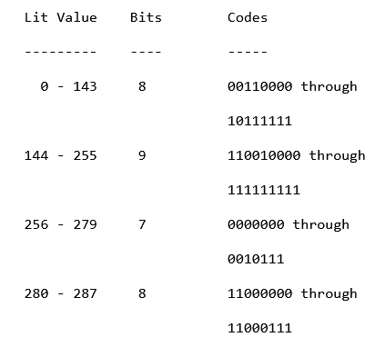
So we iterate over our binary, bit by bit. Once we reached 7 bits, we
check if the literal value of those 7 bits in integer form, is between
256 - 279, if so, we have decoded our first compressed data stream. Else,
we read one more bit, then we have two 8s. The one between 280 - 287, refers
to a position bit. This means we get a base length, and an amount of extra bits.
We then need to move from our current bit position, and capture the bits up
until the extra bits amount, and turns those into a number, and add them with our
base length. Now we have our total copies amount.
After that, we have to read an extra 5 bits, to get our distance code. Which is
also a fixed.
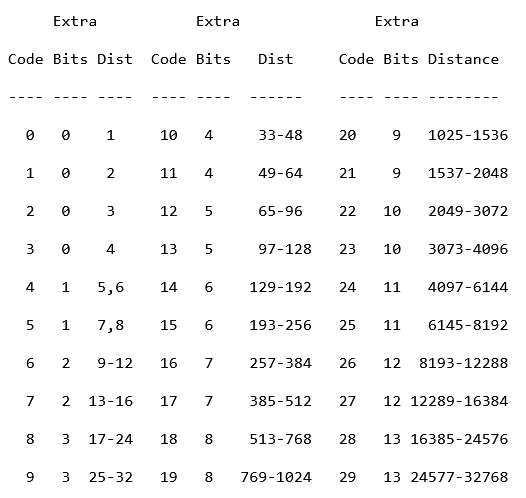
From that, we get our distance amount, and thats it.
Finally, we go to our decompressed data stream, and go back the distance amount,
and copy the total copies amount over, step by step.
So, as example. If our decoded stream looked something like "abe627cd", and our distance code is 2, and our copy code is 2. We would go back 2 bytes from the last position; "abe627 | cd", and copy the upcoming two bytes. "abe627cd | cd", making our stream like this; "abe627cdcd".
The 9 bits one works the exact same way.
The other 8 bit, is just like the 7 bits. If it matches with any found code, you convert
the bits into an integer form, and then add that to your decoded stream.
This is all you need to know about the STATIC HUFFMAN BTYPE. With this information, you should be able to decode a simple PNG file, that has a BTYPE of 01.
Well these, are WAY more complicated. But no worries.
Here are some numbers, and words.
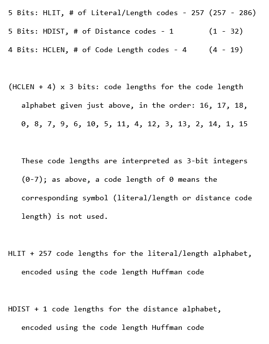
HLIT stands for Huffman Literal/Length codes, and it is basically telling us
how many length codes are used. If you re-call from our last chaper where we
covered the static huffman, you should remember the fixed huffman codes, which
ranged all the way up to 287 (though 286, and 287 are never used). Here, our
HLIT ranges from 257 to 286. So, we read our first 5 bits, and convert them
into an integer.
"01110" -> LSB -> "01110" -> 14.
We then add the 257 to the int; 257 + 14 = 271. And now know, that this dynamic
Huffman tree, contains 271 huffman codes.
HDIST are the Huffman distance codes, that we just mentioned previously. Read the
next 5 bits, lets say;
"10100" -> LSB -> "00101" -> 5.
Add a 1; 1 + 5 = 6. And now we know, we have 6 distance codes.
HCLEN are the Huffman code length codes. The size of HCLEN is 4 bits,
but you add 4 to it, and then multiply it by 3. So lets say we
have;
"0100" -> LSB -> "0010" -> 2.
Add a 4; 4 + 2 = 6. Now we know there are 6 code length codes, with the
size of 3 bits. Multiplying 6 by 3 gives us 18, so the HCLEN block takes
18 bits. The provided list is to be kept in mind, as while you are iterating
over the 18 bits, in 3 bits sections, the first 3 bits, will correspond to the
symbol within the hclen alphabet (the first one being 16).
Instantly after getting the HCLEN, go ahead and get the values for the HCLEN alphabet
(the following 18 bits). If a symbol is not even reached, or has the value of 0
you know that it is not gonna be used. We will be referring to the symbols within
the alphabet as CLS (CODE LENGTH SYMBOL), and the values of the ints will be written
as CLS(int) = value.
If you finished decoding, your CLS array might look like this;
CLS16 = 4
CLS18 = 4
CLS17 = 3
CLS0 = 2
CLS8 = 2
CLS7 = 2
Now we have the lengths, of the code length symbols. So it is time, to create
our very own huffman tree with this.
The way we do this, is kinda simple. First we take our lengths and sort them in ascending
order;
[2, 2, 2, 3, 4, 4]
Then we start.
First we check if we have created any codes up until now. No? Append "0" for the length of the first
length. So 2, meaning our first code would be "00".
We would then move on to the next length, which is also 2. We check our last code; "00", add 1 to it
(in the binary system); "01", and we created our second code.
Do the same for the next one; "01" + 1 => 10.
But for the next one, we need to be more careful. First we take our last code "10", we add 1 to it
"11", but we see that we need a length of 3, so we just append 0s to the end until it maches the length
"110". And continue.
"110", add 1 => "111", append 0s until matches length => "1110", next code.
"1110", add 1 => "1111", append 0s until matches length (already does) => "1111". Finished.
Our huffman codes look like this;
"00", "01", "10", "110", "1110", "1111". (<- The last code will always be just ones!).
Lets now assign these codes to our symbols.
CLS16 = 4
CLS18 = 4
CLS17 = 3
CLS0 = 2
CLS8 = 2
CLS7 = 2
Lets sort them in ascending order, depending on their symbol;
CLS0 = 2
CLS7 = 2
CLS8 = 2
CLS16 = 4
CLS17 = 3
CLS18 = 4
We then assign all of the codes, from the smallest code, to the
largest one, in descending order, while making sure, that the huffman
codes bits length, matches with the CLS.
CLS0 = 2 -> 00
CLS7 = 2 -> 01
CLS8 = 2 -> 10
CLS16 = 4 -> 1110
CLS17 = 3 -> 110
CLS18 = 4 -> 1111
There we have it! We assigned symbols, a huffman code! Now lets look at this image;
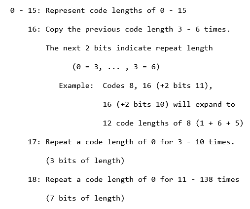
The symbols from the CLS, also have specific commands. Let me give you guys an example, REMEMBER
THE HUFFMAN CODES!
Lets say this is our binary string following the HCLEN values;
00011000001010010101101011100000110110110111100000111110011...
The way we would decode this, is again, bit by bit.
"0" -> "00" -> MATCHES WITH CLS0, so we append the literal 0 into our output storer.
00 | 01 | 10 | 00 | 00 | 10 | 10 | 01 | 01 | 01 | 10 | 10 | 1111 (0000011) | 01 | 10 | 110 | 1111 (0000011) | 1110 (011)
This is how we would get the bits for each symbol.
NOW CAUTION, this would turn into a jumbled up mess, as I am not showing an actual png. I want you to go and try it for
yourself. Use the tool infgen to compare your results with one another. If I programmed a decompressor, you can too!
Keep in mind, that you can stop iterating over the bits, once your output storers size is the size of
HLIT + HDIST + 257.
After you are done matching codes with the symbols, split the output storers output into two. From 0 all the way to
HLIT + 256. And from HLIT + 256 all the way to the end. The first split will help us build our HLIT Huffman tree, and the
second split will help us build HDIST Huffman tree.
Once you are done whining about the amount of complexity, we can continue.
Do not be suprised if the output storer contains a lot of zeros. Just make sure to skip them, because the 0s
mean, that the symbol is not being used.
And the position of a number within the output storer, also gives the symbol for the specific HLIT or HDIST. Meaning
that when we are iterating over the output storer from 0 - HLIT + 256, the indexes tell us the symbol for which the
huffman code (we will be creating) matches with. And for HDIST it is the same.
As mentioned, you know the process of creating a huffman tree already, create another one for the HLIT and HDIST.
(yes it really is necassary).
And finally, once you are done doing all of that. You should have your symbols for both HLIT and HDIST assigned to
a specific huffman code. Now, we can start re-creating the full decompressed file data.
We start again, by iterating over the left over data, bit by bit, and check for a match within our HLIT Huffman Tree. Once we find one, we match it to the symbol.
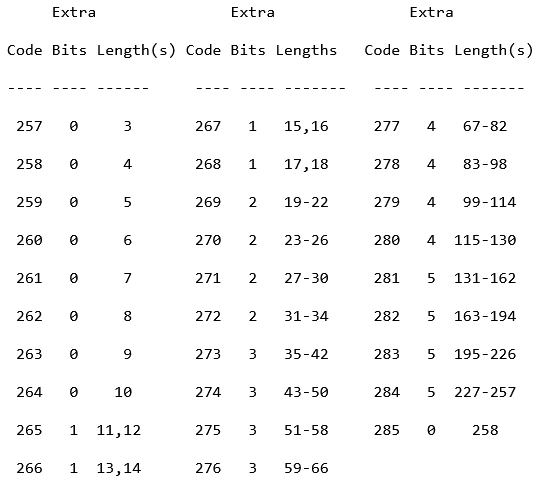
Here we can see what to do when a specific symbol is seen. If we are however, below 257, then we can again
just add the literal value into our final output storer. Else, we take the base length of the symbol. Then
read the extra bits, convert them into int (using LSB), and add them to our base length to get the total
amount of copies we need to create.
Next we start reading the following bits, until we match with a huffman code from our HDIST Huffman Tree, and match
that symbol with the ones from these images;
So, again, we read the extra bits and convert them into ints using LSB, add our base length to get our total distance we need to go back. And then it is the same game as it was in the static huffman. Go back the said distance, repeat the codes for the length of the total amount of copies needed. And keep moving until we get the HLIT Huffman code to match with the 256 symbol. If that happens, the data block ends, successfully.
I know, this might have also been a really vague explanation, but I tried my best. The creation of my own decompressor in Zig was a big challenge for me, and maybe is for some other enthusiast. I hope, that whoever reads this, or has already read this, I hope you learned something new. Thanks for reading!